Calibration is not complete until the saved file is checked
Continue after the 14-joint ID and wiring checks below. This supplement reviews the standard v2 Runtime configuration and calibration path; it is not a new image or a physical test. Keep these STS3215 settings separate from KISS HD1910 and XL330.
Choose the actual installation and configuration file
The manual-install README and docs/INSTALL.md describe different starting points. The latter describes an image with foot-switch autostart services; do not assume those services exist after a manual install. Its V2-Classic release metadata currently lists no downloadable assets, so this site has not verified a flashable ISO. If using an image with autostart, first identify and end its motion session before calibration.
DuckConfig reads the home-directory duck_config.json unless an explicit path is supplied; the walking CLI supports --duck_config_path. Back up your existing file under a new name. Copy example_config.json only for an initial setup, not over a working calibration. The standard-library command below checks JSON syntax without importing robot hardware code; it does not validate physical orientation or motor state.
python -m json.tool "$HOME/duck_config.json"
Prepare the complete configuration before motion
JSON field
What to keep explicit
start_paused
The example defaults to false. Set true for the first policy check, while keeping the separate supported-startup and power checks.
imu_upside_down
Match the actual IMU mounting and observed axes; do not copy the example value as a calibration result.
joints_offsets
Keep all 14 original joint names. The loader does not merge a partial offset dictionary with the defaults; changing one joint must not delete the other entries.
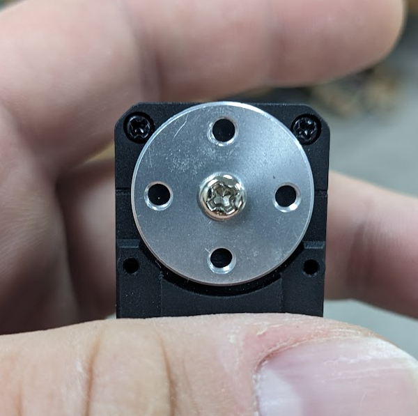
Original servo-horn alignment photo · Antoine Pirrone and contributors · Apache 2.0. Assembly reference, not a calibration or walking test by this site.
Measure, then save the confirmed offsets yourself
Before measuring, keep the robot supported and leave room for its zero pose. From Runtime/scripts, find_soft_offsets.py constructs a dummy configuration with zero offsets, not your saved calibration. It turns on the motors and commands zero before the protected per-joint loop. Only use that motion procedure after the preceding build checks; it is not a passive offset viewer.
python find_soft_offsets.py
For each joint, keep the measured value and confirmation status. The script prints the offsets and asks you to copy them into duck_config.json; it writes neither that JSON nor motor EEPROM. A skipped joint has not been measured and may remain zero in the temporary dictionary. Merge only confirmed values into your own full 14-joint joints_offsets map, preserving other entries and recording which were not remeasured.
Check the exit path and reread before first use
At this pinned revision, normal Done does not call turn_off. The KeyboardInterrupt handler covers the per-joint loop, not every startup operation, so Ctrl+C is not a blanket torque-off guarantee. Keep a reachable power cutoff and confirm the stopped state before handling. After saving, check the exact file again. Already initialized Python objects do not hot-reload it; start_paused pauses the policy loop after hardware startup and does not mean motors are off.
Record the backup and selected file paths, exact Runtime revision, all 14 joint statuses, confirmed offsets, manual save, JSON reread and stopped-state check. Unmeasured, missing or skipped checks remain open; a terminal message is not a completed hardware calibration.
Reviewed November 4, 2026 against Runtime 376de654 and design b23317a4. Documents, implementation and original photo bytes were checked; no image boot, motor movement, calibration, EEPROM write or gait test was performed here. The November 3 ID table and dated ZIP remain available below.
Before connecting the full bus: a 14-joint checklist
This fills a missing step in the existing build route using the original v2 motor guide and Runtime implementation, not a newly released robot or image. Keep the STS3215 route separate from KISS HD1910 and XL330 builds. The original wiring illustration below is now also available from the homepage.
Bus ID
Original joint name
10
right_hip_yaw
11
right_hip_roll
12
right_hip_pitch
13
right_knee
14
right_ankle
20
left_hip_yaw
21
left_hip_roll
22
left_hip_pitch
23
left_knee
24
left_ankle
30
neck_pitch
31
head_pitch
32
head_yaw
33
head_roll
The table groups right leg, left leg and head for labeling. The Runtime array order is left leg → neck/head → right leg. Numeric ID order is not policy-vector order. There is no mouth ID 34 in this standard 14-joint map.
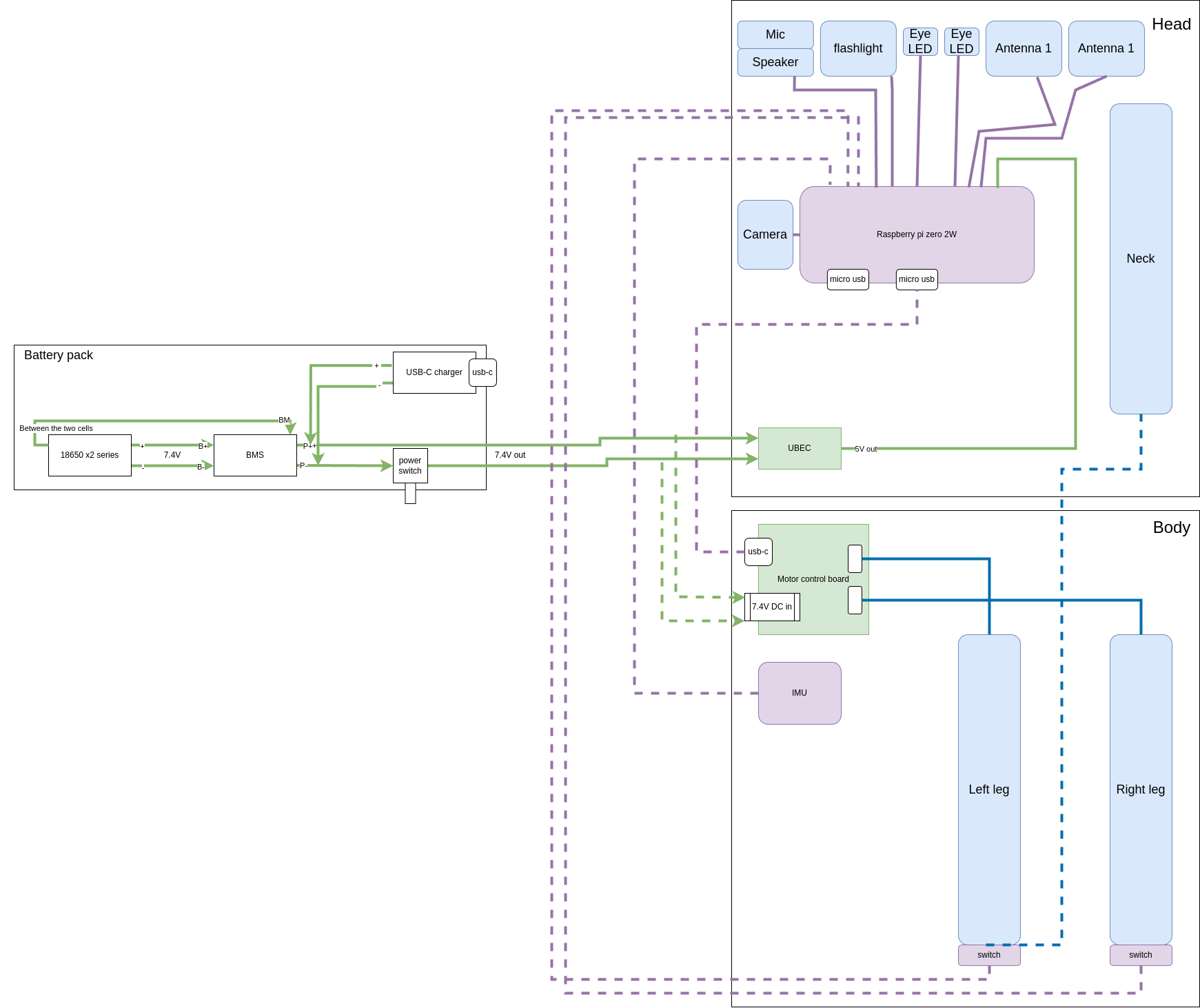
Original Open Duck Mini v2 wiring diagram · Antoine Pirrone and contributors · Apache 2.0. Source illustration, not a hardware test by this site.
With the battery disconnected, trace the original BMS/switch, servo-supply and UBEC-to-Pi branches. Distinguish Pi physical header numbers from GPIO names. Use the detailed original drawing for connector pins; the overview alone is not a pinout or permission to bypass battery protection.
After installing the matching v2 Runtime, enter its scripts directory. Connect only one unassembled motor to the compatible powered adapter, with the shaft unobstructed. configure_motor.py first probes ID 1, then scans upward and stops at the first responding ID; it is not a whole-bus inventory tool.
The example below assigns left_hip_yaw to 20. Replace the device path with your actual adapter and choose the ID from the table. /dev/ttyACM0 is only the script default. The script changes mode, acceleration and PID settings, changes the ID, then sends a zero-position target; it is not read-only.
Record the old/new ID and the printed parameter readback, then label that motor before the next one. Install the horn using the original alignment photograph after the zero movement. Encoder zero is not your measured assembly offset, and one successful motor is not a passed 14-motor bus.
The pinned HWI opens the bus at 1,000,000 baud. configure_motor.py does not set baud rate, so do not assume it repairs a previously changed motor speed. If a motor is missing, isolate it and recheck the adapter, actual port, supply and motor settings before reconnecting the full chain.
Only after wiring and labels agree, support the robot and follow the existing motor-test stage. check_motors.py writes gain settings before reading positions and can command motion. If any joint is unresponsive, decline its continue-anyway prompt and resolve that joint; do not use the script as a harmless scanner.
Keep a record for all 14 joints: physical location, ID, horn alignment, port, communication result and later individual offset. Any missing or duplicated identity stays unresolved before HOME or policy motion.
Source reviewed November 3, 2026: design b23317a4, Runtime 376de654. No motor, wiring, power, calibration or walking test was performed here. The September 9 download remains its dated historical package; this is an online checklist supplement.
Three checks before the first powered assembly test
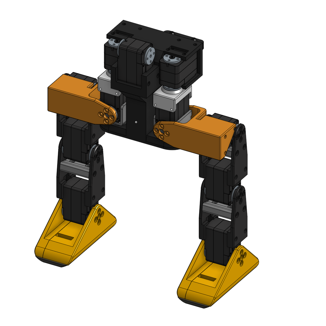
For standard Open Duck Mini v2 at b23317a. Use these cards alongside the original manual. The photos and CAD below are the original author’s references; this site has not assembled the robot.
1. Servo IDs and horn alignment
Prepare: One unassembled servo, its power and bus adapter, and the matching configure_motors instructions. Configuration writes an ID and moves the servo to zero.
Configure one servo at a time, keeping moving parts clear; fit the horn after the zero-position move.
Label left leg 20–24, right leg 10–14, neck 30 and head 31–33. Keep the original joint-name mapping.
Record the ID, horn alignment and any later calibration offset before closing the assembly.
Ready to continue when: Each of the 14 joints has one recorded ID and the horn matches the author’s reference.
If the check fails: Do not copy HD1910 zero/limit commands. Recheck the selected servo and original configuration procedure.
Copy checklist
1. Servo IDs and horn alignment
1. Servo IDs and horn alignment
Prepare: One unassembled servo, its power and bus adapter, and the matching configure_motors instructions. Configuration writes an ID and moves the servo to zero.
□ Configure one servo at a time, keeping moving parts clear; fit the horn after the zero-position move.
□ Label left leg 20–24, right leg 10–14, neck 30 and head 31–33. Keep the original joint-name mapping.
□ Record the ID, horn alignment and any later calibration offset before closing the assembly.
Ready to continue when: Each of the 14 joints has one recorded ID and the horn matches the author’s reference.
If the check fails: Do not copy HD1910 zero/limit commands. Recheck the selected servo and original configuration procedure.
2. Left and right leg assembly
Prepare: Printed leg parts, labelled servos and the original feet-to-hips assembly drawings.
Build both feet the same way; place the motor driver side as shown beside foot_top.
Use the correct left_roll_to_pitch and right_roll_to_pitch at the hips; keep left/right servo IDs attached to the corresponding leg.
Check the hip-pitch orientation, cable routing and clearance before fastening the legs to the trunk.
Ready to continue when: The two legs match the original CAD, labels are readable and no cable is pinched.
If the check fails: Return to the relevant assembly drawing. Do not use a mirrored picture as an ID or orientation reference.
Copy checklist
2. Left and right leg assembly
2. Left and right leg assembly
Prepare: Printed leg parts, labelled servos and the original feet-to-hips assembly drawings.
□ Build both feet the same way; place the motor driver side as shown beside foot_top.
□ Use the correct left_roll_to_pitch and right_roll_to_pitch at the hips; keep left/right servo IDs attached to the corresponding leg.
□ Check the hip-pitch orientation, cable routing and clearance before fastening the legs to the trunk.
Ready to continue when: The two legs match the original CAD, labels are readable and no cable is pinched.
If the check fails: Return to the relevant assembly drawing. Do not use a mirrored picture as an ID or orientation reference.
3. Power, bus and IMU wiring
Prepare: A disconnected battery, the original overview/detail wiring diagrams and the Runtime configuration.
Trace battery, BMS and servo power against the diagram, checking polarity and connector pin numbers.
Supply the Pi through the separate regulated 5 V path. Never connect battery voltage directly to the Pi 5 V pin.
Compare the IMU mounting and runtime orientation, and confirm how power can be disconnected before starting calibration.
Ready to continue when: The disconnected wiring has been checked against both original diagrams and the matching configuration.
If the check fails: Keep power disconnected until the mismatch is understood. Do not bypass battery protection to diagnose a restart.
Copy checklist
3. Power, bus and IMU wiring
3. Power, bus and IMU wiring
Prepare: A disconnected battery, the original overview/detail wiring diagrams and the Runtime configuration.
□ Trace battery, BMS and servo power against the diagram, checking polarity and connector pin numbers.
□ Supply the Pi through the separate regulated 5 V path. Never connect battery voltage directly to the Pi 5 V pin.
□ Compare the IMU mounting and runtime orientation, and confirm how power can be disconnected before starting calibration.
Ready to continue when: The disconnected wiring has been checked against both original diagrams and the matching configuration.
If the check fails: Keep power disconnected until the mismatch is understood. Do not bypass battery protection to diagnose a restart.
The original guide specifies PLA at 15% infill; only foot_bottom_tpu.stl uses TPU at 40%. Layer height, wall count, supports, orientation and temperatures are not fully specified. Trial-fit a foot and a structural joint before printing the batch. File links below open the pinned originals.
Applies to Open Duck Mini v2. This independent reading route connects the original project’s documents. It does not certify a completed build by this site. Use the linked photographs and diagrams during assembly; they carry details a text overview cannot replace.
1. Fix the design and prepare the budget.
Open the original project hub ↗ and original bill of materials ↗. Save a dated copy before shopping. The author-linked Tnkr guide ↗ also presents components and quantities: its reviewed table lists 14 Feetech 7.4 V STS3215 servos, a Raspberry Pi Zero 2 W and a BNO055 IMU. This is a starting inventory, not the whole shopping list.
Price the exact variant, delivered quantity, shipping, printed parts, tools and replacements in your own location. The project’s historical sub-$400 target is not a current checkout quote. Do not treat two listings with a similar servo name as equivalent.
Checkpoint: every part has a source, variant and quantity; every substitution has an unresolved compatibility note until checked.
2. Print and inspect the parts.
The original print guide ↗ specifies PLA at 15% infill, except foot_bottom_tpu.stl, which uses TPU at 40%. It lists quantities for each file. Follow those counts: several leg pieces need four copies, and mirrored left/right parts are distinct.
Record your printer, material and slicer settings. Inspect a sample joint and insert fit before repeating a whole batch. File the results in your build log so a later reprint uses the same baseline.
Checkpoint: the print list is accounted for and you can identify each mirrored pair. Download fabrication files from this design, rather than MicroDuck simulation meshes.
3. Give each servo its identity before assembly.
Install the v2 runtime on your computer or Raspberry Pi using the runtime setup instructions ↗ before this step; the motor guide permits either machine. The original procedure configures one motor at a time and moves it to a reference position before horn fitting. Follow the motor configuration guide ↗ and inspect the actual configuration script ↗. It writes settings and commands motion; this is not a passive discovery command.
Reference servo IDs for Open Duck Mini v2 only
Joint
Left
Right
Hip yaw
20
10
Hip roll
21
11
Hip pitch
22
12
Knee
23
13
Ankle
24
14
Neck pitch is 30; head pitch, yaw and roll are 31, 32 and 33. Label the configured motors before you put them into the structure.
Inspect configuration options from the installed runtime repository
python scripts/configure_motor.py --help
The reviewed script lives in scripts/ and accepts --port and --id. Its default port is /dev/ttyACM0; use the actual connected device. In a manufacturer tool, confirm position units before entering a value: a library’s zero angle is not necessarily raw encoder zero.
For example, with only the unassembled left hip-yaw servo connected and free to move, the following assigns ID 20. Replace the port with your device; configure the remaining motors individually using the table.
Checkpoint: each motor has a unique label and the intended reference position. Finish this stage before locking in the horn orientation.
4. Assemble the structure with the illustrated guide.
Work through the original assembly photographs ↗: trunk, feet, shins, thighs, hips, neck, head and body. Follow the cable-routing steps before closing a joint. The guide calls for a little threadlocker on metal-to-metal motor screws, with a separate instruction not to use it on plastic screws.
The reviewed document still leaves the exact M3 screw total, a servo-board photo and some expression-feature instructions unfinished. Check the interactive assembly guide ↗ for additional views; resolve any remaining fit or mounting question before proceeding.
Checkpoint: parts sit in the shown orientation and moving joints leave room for cables. Save photos before closing the shell.
5. Check wiring and sensor orientation.
Use the electronics diagram and pin tables in the same assembly revision ↗. They distinguish physical pin numbers from BCM GPIO numbers. Trace each connection against the correct column. The IMU note also explains that an older photo shows an upside-down mounting.
Before connecting power, confirm polarity, the specified supply for each board and isolation from exposed conductors. Battery-pack assembly needs suitable electronics skills; use the original battery instructions and component specifications, not a generic three-wire colour assumption.
Checkpoint: record the diagram revision, your IMU orientation and any wiring changes. A photograph of someone else’s build does not confirm your connections.
6. Prepare the Raspberry Pi using one install route.
Image availability: the image instructions ↗ describe a pre-built setup for reference Raspberry Pi Zero 2 W hardware. However, our check of public releases ↗ found a V2-Classic source release with no attached image files. We could not verify the advertised image download, so use the manual route below. If an image becomes available, check its hardware match, configure your own credentials and complete calibration.
Manual route: follow the runtime README ↗ for Raspberry Pi OS Lite 64-bit, interfaces, controller pairing and its Python environment. Use a separate checkout for the reviewed runtime revision:
Create a checkout of the reviewed Open Duck Mini runtime
git clone https://github.com/apirrone/Open_Duck_Mini_Runtime Open_Duck_Mini_Runtime-reviewed
cd Open_Duck_Mini_Runtime-reviewed
git checkout --detach 376de65435c93486347cd601a31aa96951799896
Then complete dependency installation in the environment described by that README. Record an image release or source revision in the log so future debugging starts from the same setup.
7. Calibrate this robot and test its inputs.
Use the runtime instructions to create ~/duck_config.json, check the IMU and measure the joint offsets. The example configuration ↗ separates IMU orientation, joint offsets and optional expression features. Fill these from your build; another maker’s offset values are not your calibration.
The motor-check script ↗ enables torque and offers movement tests. Support the robot with joint clearance before using it, and read each prompt. Stop on a failed motor response instead of treating the rest of the test as a pass.
Use the original pre-policy checklist ↗ to check joint positions and offsets, IMU orientation and foot switches. Keep optional eyes, antennas, speaker and camera checks separate. Confirm the gamepad responds before attempting walking.
Checkpoint: save your configuration and record each input’s observed response. A successful installation alone does not pass this stage.
For this runtime, the gamepad A button toggles policy pause. Pause does not mean motor power is disconnected: the script turns the hardware on before its control loop. Keep the physical power switch reachable. The example configuration also defaults start_paused to false; choose the intended startup state before running.
After the checks above, activate the installed runtime environment, enter its scripts/ directory and use the original command form below. Replace the model path with the file you downloaded for this robot.
Start with a short observation, stop, inspect the robot, and record what happened. Use only the policy format and hardware combination documented for this runtime. A MicroDuck ONNX file is not a drop-in Open Duck Mini policy.
Training a new gait comes later. The project’s sim-to-real notes ↗ explain the robot model, actuator identification, Open Duck Playground and reference-motion route; that document is itself marked unfinished.
Keep a record you can resume.
Open Duck Mini build record
Robot: Open Duck Mini v2
Hardware repository revision: b23317a485b3cec7d8417f352478778b3475173c
Runtime repository revision or image release:
BOM saved on / local delivered cost:
Printed parts revision / material / slicer settings:
Servo model and ID labels:
Wiring diagram revision / changes:
IMU orientation / calibration result:
Joint offsets file backed up to:
Foot-switch and controller checks:
Policy filename / source / hash:
First trial conditions and observed result:
Unresolved issue / next check:
Original Open Duck Mini v2 diagrams · Antoine Pirrone’s repository · Apache 2.0. The Pi uses a separate 5 V regulator; do not connect the battery rail directly to the Pi 5 V pin.