Open Duck Mini v2 · print files & assembly
36 original STL files · 51 printed parts · 49 PLA + 2 TPU. Includes two original wiring diagrams, an English print guide and a detailed Chinese assembly guide.
Version, license & file checks
Standard v2 files from Antoine Pirrone’s Open Duck Mini repository, unchanged. Includes the upstream Apache 2.0 license and attribution. These files belong to Open Duck Mini v2. Physical printing, fit and walking have not been tested by this site.
Commit b23317a485b3cec7d8417f352478778b3475173c
ZIP SHA-256 0d68bcf6650be56e26c40d463202a1c78980fc3e4f45258955eef1227beb3145
Complete print list: 36 files, 51 parts
The original guide specifies PLA at 15% infill; only foot_bottom_tpu.stl uses TPU at 40%. Layer height, wall count, supports, orientation and temperatures are not fully specified. Trial-fit a foot and a structural joint before printing the batch. File links below open the pinned originals.
1. Fix the design and prepare the budget.
Open the original project hub ↗ and original bill of materials ↗. Save a dated copy before shopping. The author-linked Tnkr guide ↗ also presents components and quantities: its reviewed table lists 14 Feetech 7.4 V STS3215 servos, a Raspberry Pi Zero 2 W and a BNO055 IMU. This is a starting inventory, not the whole shopping list.
Price the exact variant, delivered quantity, shipping, printed parts, tools and replacements in your own location. The project’s historical sub-$400 target is not a current checkout quote. Do not treat two listings with a similar servo name as equivalent.
Checkpoint: every part has a source, variant and quantity; every substitution has an unresolved compatibility note until checked.
2. Print and inspect the parts.
The original print guide ↗ specifies PLA at 15% infill, except foot_bottom_tpu.stl, which uses TPU at 40%. It lists quantities for each file. Follow those counts: several leg pieces need four copies, and mirrored left/right parts are distinct.
Record your printer, material and slicer settings. Inspect a sample joint and insert fit before repeating a whole batch. File the results in your build log so a later reprint uses the same baseline.
Checkpoint: the print list is accounted for and you can identify each mirrored pair. Download fabrication files from this design, rather than MicroDuck simulation meshes.
3. Give each servo its identity before assembly.
Install the v2 runtime on your computer or Raspberry Pi using the runtime setup instructions ↗ before this step; the motor guide permits either machine. The original procedure configures one motor at a time and moves it to a reference position before horn fitting. Follow the motor configuration guide ↗ and inspect the actual configuration script ↗. It writes settings and commands motion; this is not a passive discovery command.
| Joint | Left | Right |
|---|---|---|
| Hip yaw | 20 | 10 |
| Hip roll | 21 | 11 |
| Hip pitch | 22 | 12 |
| Knee | 23 | 13 |
| Ankle | 24 | 14 |
Neck pitch is 30; head pitch, yaw and roll are 31, 32 and 33. Label the configured motors before you put them into the structure.
python scripts/configure_motor.py --helpThe reviewed script lives in scripts/ and accepts --port and --id. Its default port is /dev/ttyACM0; use the actual connected device. In a manufacturer tool, confirm position units before entering a value: a library’s zero angle is not necessarily raw encoder zero.
For example, with only the unassembled left hip-yaw servo connected and free to move, the following assigns ID 20. Replace the port with your device; configure the remaining motors individually using the table.
python scripts/configure_motor.py --port /dev/ttyACM0 --id 20Checkpoint: each motor has a unique label and the intended reference position. Finish this stage before locking in the horn orientation.
4. Assemble the structure with the illustrated guide.
Work through the original assembly photographs ↗: trunk, feet, shins, thighs, hips, neck, head and body. Follow the cable-routing steps before closing a joint. The guide calls for a little threadlocker on metal-to-metal motor screws, with a separate instruction not to use it on plastic screws.
The reviewed document still leaves the exact M3 screw total, a servo-board photo and some expression-feature instructions unfinished. Check the interactive assembly guide ↗ for additional views; resolve any remaining fit or mounting question before proceeding.
Checkpoint: parts sit in the shown orientation and moving joints leave room for cables. Save photos before closing the shell.
5. Check wiring and sensor orientation.
Use the electronics diagram and pin tables in the same assembly revision ↗. They distinguish physical pin numbers from BCM GPIO numbers. Trace each connection against the correct column. The IMU note also explains that an older photo shows an upside-down mounting.
Before connecting power, confirm polarity, the specified supply for each board and isolation from exposed conductors. Battery-pack assembly needs suitable electronics skills; use the original battery instructions and component specifications, not a generic three-wire colour assumption.
Checkpoint: record the diagram revision, your IMU orientation and any wiring changes. A photograph of someone else’s build does not confirm your connections.
6. Prepare the Raspberry Pi using one install route.
Image availability: the image instructions ↗ describe a pre-built setup for reference Raspberry Pi Zero 2 W hardware. However, our check of public releases ↗ found a V2-Classic source release with no attached image files. We could not verify the advertised image download, so use the manual route below. If an image becomes available, check its hardware match, configure your own credentials and complete calibration.
Manual route: follow the runtime README ↗ for Raspberry Pi OS Lite 64-bit, interfaces, controller pairing and its Python environment. Use a separate checkout for the reviewed runtime revision:
git clone https://github.com/apirrone/Open_Duck_Mini_Runtime Open_Duck_Mini_Runtime-reviewed
cd Open_Duck_Mini_Runtime-reviewed
git checkout --detach 376de65435c93486347cd601a31aa96951799896
Then complete dependency installation in the environment described by that README. Record an image release or source revision in the log so future debugging starts from the same setup.
7. Calibrate this robot and test its inputs.
Use the runtime instructions to create ~/duck_config.json, check the IMU and measure the joint offsets. The example configuration ↗ separates IMU orientation, joint offsets and optional expression features. Fill these from your build; another maker’s offset values are not your calibration.
The motor-check script ↗ enables torque and offers movement tests. Support the robot with joint clearance before using it, and read each prompt. Stop on a failed motor response instead of treating the rest of the test as a pass.
Use the original pre-policy checklist ↗ to check joint positions and offsets, IMU orientation and foot switches. Keep optional eyes, antennas, speaker and camera checks separate. Confirm the gamepad responds before attempting walking.
Checkpoint: save your configuration and record each input’s observed response. A successful installation alone does not pass this stage.
8. Try the matching first-walk policy.
The runtime first-walk section ↗ links BEST_WALK_ONNX_2.onnx for this robot. Keep its source with your runtime version. Review the walking script and controls ↗ before launching it in a clear, supported test area.
For this runtime, the gamepad A button toggles policy pause. Pause does not mean motor power is disconnected: the script turns the hardware on before its control loop. Keep the physical power switch reachable. The example configuration also defaults start_paused to false; choose the intended startup state before running.
After the checks above, activate the installed runtime environment, enter its scripts/ directory and use the original command form below. Replace the model path with the file you downloaded for this robot.
python v2_rl_walk_mujoco.py --onnx_model_path /absolute/path/BEST_WALK_ONNX_2.onnxStart with a short observation, stop, inspect the robot, and record what happened. Use only the policy format and hardware combination documented for this runtime. A MicroDuck ONNX file is not a drop-in Open Duck Mini policy.
Training a new gait comes later. The project’s sim-to-real notes ↗ explain the robot model, actuator identification, Open Duck Playground and reference-motion route; that document is itself marked unfinished.
Keep a record you can resume.
Robot: Open Duck Mini v2
Hardware repository revision: b23317a485b3cec7d8417f352478778b3475173c
Runtime repository revision or image release:
BOM saved on / local delivered cost:
Printed parts revision / material / slicer settings:
Servo model and ID labels:
Wiring diagram revision / changes:
IMU orientation / calibration result:
Joint offsets file backed up to:
Foot-switch and controller checks:
Policy filename / source / hash:
First trial conditions and observed result:
Unresolved issue / next check:Original wiring diagrams
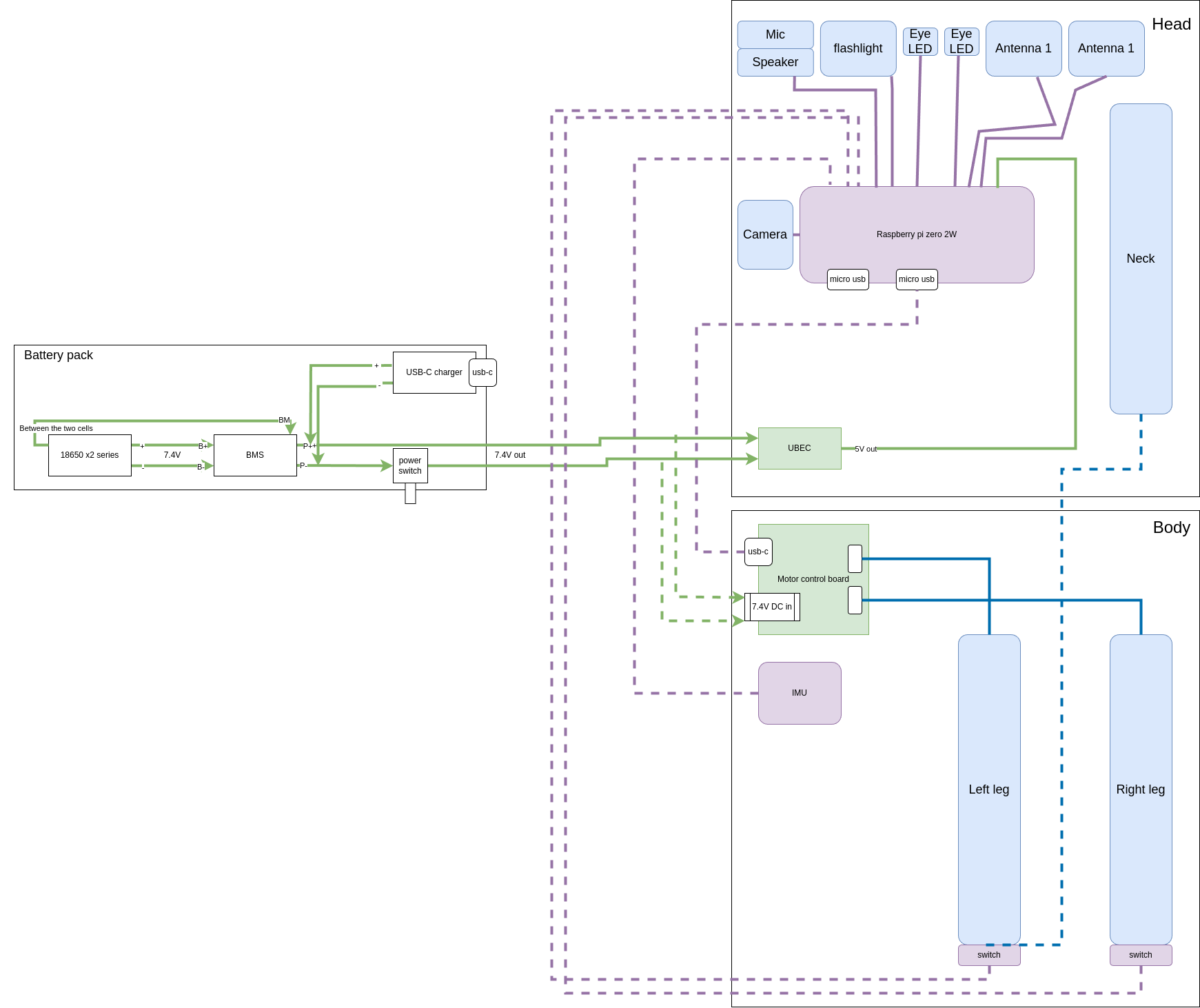
Open the full-resolution detailed wiring diagram ↗
What would you like to understand next?
Keep the source, your environment and your observations together.